Metamaterials and Reconfigurable Intelligent Surfaces
by Vladan Jevremovic, PhD
Introduction
Metamaterials are a new class of artificial materials, whose microstructure is engineered to exhibit unique electromagnetic properties not observed in nature, and previously believed to be physically inconceivable [1]. All materials found in nature have periodic structure that consists of atoms. In metamaterials, an artificial periodic structure is created and inserted onto a host material. This artificial periodic structure has constituent elements that are larger than the host material atoms. This size difference has the effect of overriding the natural response of the underlying host material to the incoming electromagnetic wave. Thus, the resulting penetration and reflection loss as well as reflection angle are specific to the artificial structure and not to the underlying atomic structure of the host material. In this paper we talk about the key metamaterial features, introduce the concept of Reconfigurable Intelligent Surface (RIS) and describe the potential RIS use cases in modern wireless communications.
Key metamaterials features
A metamaterial (from the Greek word meta, meaning “beyond” and the Latin word matera, meaning “matter”) is any artificially engineered material to have a property that is not found in naturally occurring materials. A metamaterial microstructure is artificially designed such that the emerging effective macroscopic response of the structure to a given excitation is not readily encountered in nature [1]. Artificially designed periodic structures within metamaterial can be made of metal, plastic, or semiconductor. A repeating pattern of the periodic structure is called “meta-atom”, and its size must be much less than the wavelength of the electromagnetic wave that interacts with the metamaterial. This is necessary because the periodic structure must appear uniform to the incoming wave. Some authors propose that for the uniformity principle to hold, the meta-atom size p must be less than a quarter of the wavelength:
p ≤λ/4
A material interaction with the electromagnetic wave is quantified through refractive index n through its constitutive parameters, the relative permittivity ε, and relative permeability µ
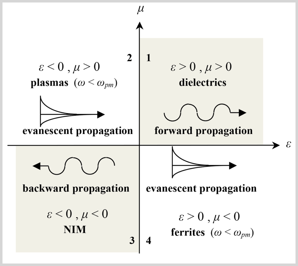
Most materials found in nature have positive permeability and permittivity. Those materials are called dielectrics and are characterized by forward electromagnetic wave propagation, when group velocity and phase velocity travel in the same direction and the energy flow is in the same direction as the motion of the wave pattern. Ferrites (ε > 0, µ <0), and plasma (ε < 0, µ > 0), have negative εµ product and refraction index is pure imaginary number, which results in lossy propagation through material. This is also known as evanescent propagation.
The most interesting case is when both constitutive elements are negative. Even though both constituent elements are negative, their product is positive, and the refraction index is a real number. These materials are called Negative Index Materials (NIM) [2]. They are characterized by backward propagation, when group velocity and phase velocity travel in the opposite direction and the energy flow is in the reverse direction to the motion of the wave pattern. There are no known natural NIM materials and creating an artificial material with NIM is the focus of metamaterial research. Forward, backward and evanescent propagation are shown in the µε diagram below:
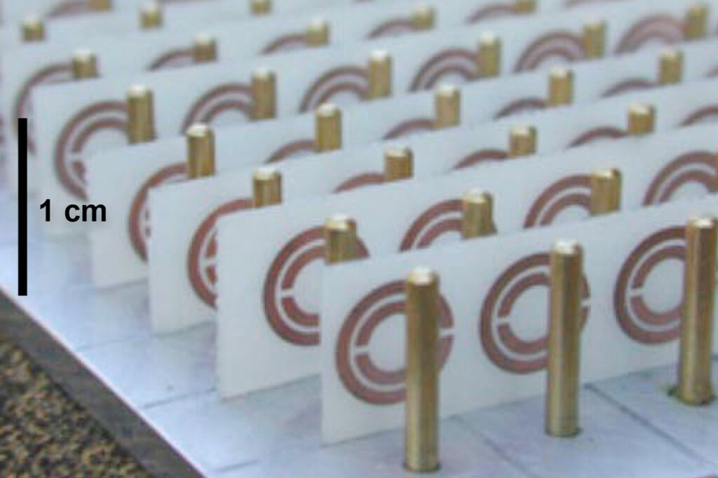
Negative Refractive Index (NRI) materials were first theoretically predicted in 1968 by Victor Veselago [3]. One possible way to create an NRI metamaterial is to create alternating layers of thin wire media made of metallic nanorods (negative ε) and layers of circular split ring resonators (negative μ), and stack them on top of each other:
Reconfigurable Intelligent Surfaces (RISs)
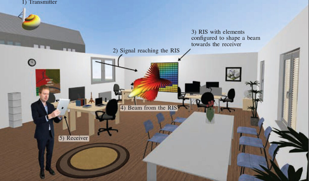
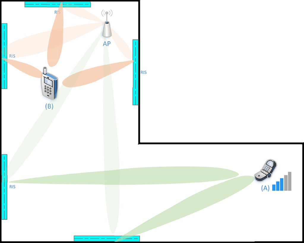
An RIS is a thin surface composed of N elements, each being a small antenna that receives and passively re-radiates with a configurable time delay. For narrowband signals, this delay corresponds to a phase shift. Assuming the phase shifts are properly adjusted, the scattered waves add constructively at the receiver. This principle resembles traditional beamforming; each element has a fixed radiation pattern, but the collection of phase shifts determines where constructive interference among the scattered waves occurs.
In its most simplest form, an RIS can be implemented as a dynamic reflectarray, whose elements are omnidirectional antennas with controllable termination that can be changed dynamically to backscatter and phase shift the incident waveform. A more elaborate implementation would be using a dynamically tunable metasurface, a 2D planar form of metamaterials that has been shown to possess great electromagnetic wave manipulation capabilities. Relying on the metasurface implementation, an RIS element can not only scatter and phase-shift the signal but can also act as an anomalous mirror with a controllable reflection angle and even polarization manipulation abilities.
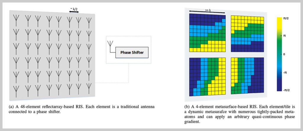
In essence, any passive surface that can be dynamically reconfigured to manipulate incident electromagnetic waves and change the channel conditions can be called an RIS. The reflectarray based RIS shown in Figure 4a can be thought of as providing powerful centralized analog beamforming capabilities in advantageous locations that can be utilized by communication endpoints. The dimension of each element in reflectarray based RIS individually acts as a diffuse scatterer.
Earlier metasurfaces designs have been based on static preset meta-atoms designs that cannot be modified after fabrication. However, later designs rely on semiconductor components, which can be reconfigured in real-time to change the underlying meta-atom structure and hence the electromagnetic behavior of the metasurface. This reconfigurability is achieved by integrating components that can be tuned either electrically, mechanically, or thermally. Electrically tunable metasurfaces are especially attractive since they can be cheaply manufactured using well-understood semiconductor technologies and can be tuned fast enough to adapt to the time-varying wireless communication channel by incorporating varactor diodes or liquid crystals within the meta-atoms. A metasurface-based RIS, illustrated in Figure 4b, is comprised of several tiles and each tile is an individually reconfigurable metasurface whose dimensions are much larger than the wavelength. This allows a large degree of flexibility in manipulating the incident wavefront. For example, each tile can reflect the incident wavefront in a different direction.
In general, the ability to optimize the RIS configuration is limited by available information about the relevant channels. Without at least partial knowledge about the underlying propagation environment, the RIS cannot be used effectively to improve the system performance. Unlike the traditional wireless systems where channel acquisition is a straightforward matter by utilizing pilot signals, RIS wireless systems are more difficult given the passive nature of the RIS and the massive number of channel parameters to be estimated.
There are two approaches from the literature to tackle the problem of optimizing the RIS configuration with limited channel information. The first approach is to forgo channel estimation altogether; instead, the optimization of the RIS can be based on feedback from the receiver. This can be done using a predefined codebook of beam directions; however, the size of the codebook will be proportional to the number of elements. If there are many RIS elements, training may take a long time. This can be a problem in a dynamic environment where the channel coherence time is limited. Nevertheless, relying on feedback from the receiver is a promising solution, and most empirical studies have built prototype systems that rely on receiver feedback to guide the optimization of the RIS configuration without explicit knowledge of the channels involved.
The other approach is to equip a small subset of the RIS elements with low-power active receivers that can process pilots and estimate the relevant channels. This approach on its own does not provide enough information to facilitate beamforming; however, by leveraging tools from compressed sensing and machine learning, the limited available information can be used to compute sufficiently accurate estimates at all channel elements. It has been shown that only 1% of the RIS elements need to be active in practical propagation scenarios to support a sufficiently accurate prediction of the channels [5].
Basic RIS features
The achievable data rate over a wireless communication channel is limited by the order of the modulation, the number of spatial streams, and interference in the channel. A user far away from the transmitter will be forced to use lower rate modulation, and thus will have a lower data rate. A line of sight (LOS) link may enjoy high communication channel gain but will probably suffer from a lack of multipath, limiting the number of spatial streams and consequently limiting the achievable data rate. The propagation characteristics at the higher frequency bands (30-100 GHz) will give rise to these scenarios more often. RIS can be used to alter wireless channel in these scenarios and improve overall system performance dramatically.
The presence of the RIS in the middle of the propagation environment provides a unique opportunity to alter the wireless channel in ways not possible by traditional MIMO arrays. The RIS can be used to keep the wireless channel well-conditioned, which increases the achievable data rate. RIS can also be used to mitigate the effects of Doppler spread and multipath fading. The RIS can operate in multiple modes to satisfy diverse objectives [4], [5]:
As a large analog beamformer to focus power to a single antenna receiver
To enhance channel rank and condition number to facilitate spatial multiplexing
To reduce interference and allow spectrum sharing
To mitigate the Doppler spread
To reduce eavesdropping by limiting signal leakage outside the intended area
Sparse environment sensors can be deployed to monitor the propagation environment and provide information to a centralized controller. This information can be in form of partial channel coefficients or user positions. The vast potential of RIS in shaping the radio environment will be limited only by the ability to find good configurations efficiently within the channel coherence interval.
There is no doubt that RIS can be used for fixed communication links, but mobile operation requires real-time channel estimation and reconfiguration, even in indoor use cases. A few millimeters of movement will change the channels in frequencies of 28 GHz and above. It remains to be demonstrated if any estimation protocol can enable real-time reconfigurability and under what mobility conditions. The RIS will require a power source for reconfigurability and wireless control channels. It is likely that the control interface will consume most of the power at the RIS, so one cannot predict the total power consumption until the channel estimation and reconfigurability have been solved and validated.
RIS use cases
An immense amount of time and resources are required to bring a new technology concept, such as RIS, from theory to practice. Very convincing benefits compared to existing technologies must be established to motivate such investment; we essentially need to demonstrate 10 times improvements with respect to a practically important performance metric, not just 20 percent gains that might disappear in an imperfect implementation [4]. MIMO and mmWave communications passed this test in 5G development since the former can increase the number of served users by 10 times, while the latter can increase the data rate per user 10 times using much wider bandwidth.
To motivate the practical development of RIS technology, the critical question is: what is the convincing use case? The answer is not clear. Coverage extension is one option, but since each RIS element must be identically configured over the entire frequency band, the RIS technology is not fit for wideband channels. Improved spatial multiplexing and interference mitigation represents another use case, but it competes against massive MIMO. Another potential use case is in TeraHertz, where the implementation of coherent transceivers is truly challenging, and the sparse channels make additional propagation paths useful, even if they are weak. The last use case may show the most promise, but there is no hard evidence yet.
RIS propagation modelling
The propagation analysis of an RIS entails the following steps [4]:
Finding the Green’s function of the signal source, which is a sum of spherical waves if the signal source is close, or a plane wave if far away
Computing the impinging field at each RIS element
Integrating this field over the surface of each element to find the current density
Computing the radiated field from each element
Applying the superposition principle to find the field at the receiver
Full wave EM simulation can fully capture the interaction of an incoming wave with RIS and compute the reflected fields both in the near and the far field of the surfaces. However, applying full wave analysis to a realistic communication channel, such as an office building, requires extremely large memory and CPU time. Ray tracing, an asymptotic method that has been widely used for propagation modeling, is an efficient alternative. In [6], the authors propose an efficient hybrid modeling method. The method requires full wave simulation to get the radiation pattern of the transmitter and the complex radar cross section (RCS) of the RIS. The complex RCS is used to implement the RIS as a secondary radiation source in the ray traces. This method enables the direct integration of RIS into ray tracing. The modeling procedure can thus be summarized as follows:
Ray trace the transmitting antenna excluding the RIS to obtain the electric field Ē1 everywhere
Using ray tracing, compute the total received power at the RIS, PRIStot
Compute the complex RCS of the RIS using full wave analysis
Ray trace the scattered rays excluding the transmitter to obtain the electric field Ē2 everywhere due to the RIS
The total electric field is: Ē = Ē1 + Ē2
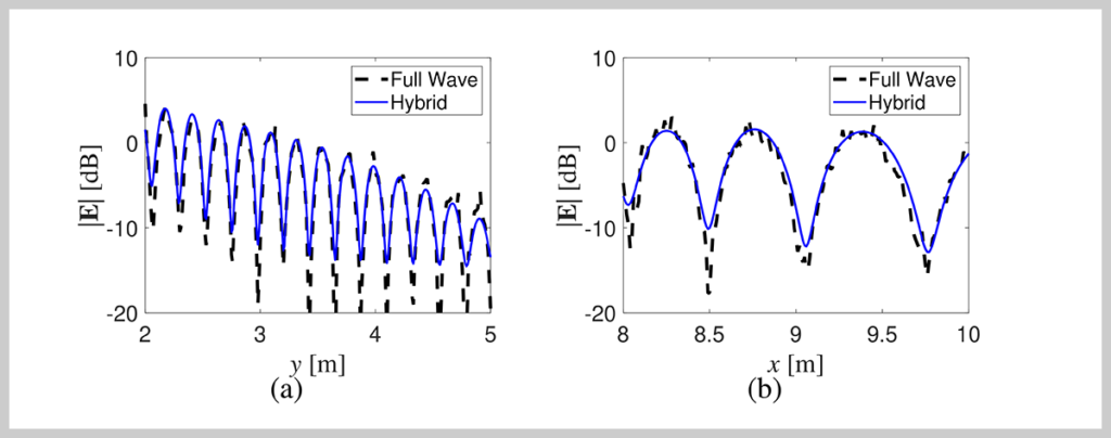
In the same paper the authors compare the magnitude of the electric field of the hybrid method with full wave analysis using HFSS:
It is clear that the proposed hybrid method has very good accuracy compared to traditional full wave propagation analysis.
Another method, proposed in [7] develops a closed form large-scale path loss equation, and gives path loss approximation in the RIS near field and far field:
PLNEAR FIELD~ (d1+d2)2
PLFAR FIELD~ (d1d2)2
Where d1 is the distance from the transmitter to the RIS, and d2 is the distance from the receiver to the RIS.
If the distances are equal (d1 = d2 = d), the near field path loss is proportional to 4d2, and the far field path loss is proportional to d4. This means that path loss increases much faster once the receiver/transmitter is in the RIS far field. The boundary between the near and far field is given as L= 2D2/λ, where D is the largest dimension of the RIS. If the RIS is a square with sides of 1.5 meters, and if the transmitting frequency is 30 GHz, then the boundary is at L = 900 meters. For most practical indoor applications, the transmitter and receiver are in the near field of the RIS.
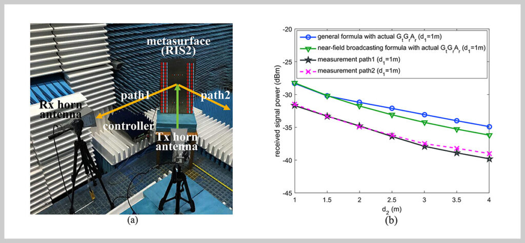
For verification purposes, the measurement test bed was set up in a microwave anechoic chamber. They utilized three different metasurfaces to act as RISs in three different scenarios. The setup and the measurements for the intelligent reflection through the large RIS (Scenario 2) is shown below:
In the setup, the RIS reflects the incoming signal, which is at the distance d1, along two distinct paths, Path 1 and Path 2. The distance d1 is fixed at 1 meter, while the signal was measured along Path 1 and Path 2 at distances d2 = 1 to 4 meters.
From Figure 4b it is apparent that the difference between the calculated and measured power at the receiver is in the 3-4 dB range. This error is rather large, given that this setup was measured in a controlled environment (anechoic chamber). Therefore, the usefulness of this path loss approximation formula is limited.
Summary
In this paper we gave an overview of metamaterials and Reconfigurable Intelligent Surfaces (RISs). The main features of RIS were identified as coverage enhancement, channel rank enhancement, interference suppression, and Doppler spread mitigation. Several potential use cases have been identified, with TeraHertz signal enhancement looking like the most promising one. We presented implementation challenges and identified designing the practical protocols for real-time reconfigurability as the most important one. Finally, we presented two approaches to EM signal propagation modeling in the presence of RIS: a hybrid ray tracing approach, and a large-scale path loss near/far field approximation.
References
[1] Ung, Bora. (2008). Metamaterials: a metareview. Optics Photonics News Phys. Rev. Lett. Phys.
[2] J. B. Pendry, “Negative Refraction Makes a Perfect Lens,” Phys. Rev. Lett. 85, 3966-3969 (2000).
[3] V. G. Veselago, Sov. Phys. USPEKHI 10, 509–514 (1968)
[4] E. Bjorrnson, O. Ozdogan, E,G, Larsson: “Reconfigurable Intelligent Surfaces: Three Myths and Two Critical Questions”, IEEE Communications Magazine, December 2020
[5] M.A. ElMosallamy, H. Zhang, L. Song, K.G. Seddik, Z. Han, G.Y. Li: “Reconfigurable Intelligent Surfaces for Wireless Communications: Principles, Challenges, and Opportunities” , IEEE Transactions on Cognitive Communications and Networking, Vol6, No3, September 2020
[6] Y. Liu, C.D. Saris: “Hybrid Full-Wave/Ray Tracing Propagation Modelling of Reconfigurable Intelligent Surface Enabled Communication Channels”, to appear in IEEE Antennas and Wireless Propagation Letters, 2022
[7] W. Tang, M Z. Chen, X. Chen, J.Y. Dai, Y. Han, M. Di Renzo, Y. Zeng, S. Jin, Q. Cheng, T. J. Ciu: “Wireless Communications with Reconfigurable Intelligent Surface: Path Loss Modeling and Experimental Measurement”, IEEE Transactions on Wireless Communications Vol20, No1, January 2021
About iBwave
iBwave Solutions, the standard for converged indoor network planning, is the power behind great in-building wireless experience, enabling billions of end users and devices to connect inside a wide range of venues. As the global industry reference, our software solutions allow for smarter planning, design and deployment of any project regardless of size, complexity or technology. Along with innovative software, we are recognized for world class support in 100 countries, industry’s most comprehensive components database and a well established certification program. For more information visit: www.ibwave.com


